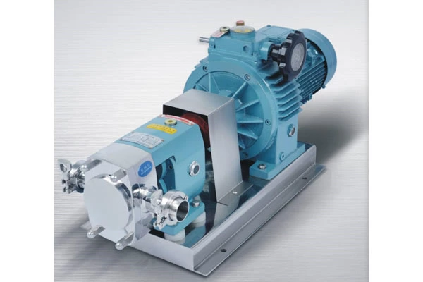
Sanitary Rotor Pump YUY-Z
- Specifications:
- 0.55KW-22KW
- Material:
- SUS304,SUS316L
- Speed:
- 200-900(rpm)
Introduction to sanitary rotor pump:
The YUY-Z series sanitary rotor pump is a kind of rotary displacement pump specially used to convey products of high viscosity researched and developed by Yuanya Company. It is mainly applied in such industries as food,bewerage,chemical industry,medicine,etc. By integrating the latest sanitary design concepts,the products can meet the increasing requirements for sanitation and cleanliness in different service conditions.
Specialized manufacturing technology and machining precision of the products have reached internationally advanced level,making their quality more stable with high efficiency and good safety,and becoming the preferred choice of clients all over the world.
The sanitary rotor pump is a kind of displacement pump,which is also called cam pump,colloid pump,three-vane pump and universal conveying pump. It realizes the purpose of conveying fluids through periodic transformation of multiple fixed volume conveying units inside the working chamber.
Working principle of sanitary rotor pump:
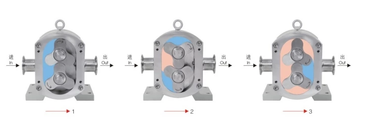
As shown in the figure, due to continuous movement of the two rotors, the media are transported to the discharging port in the volume flow direction through the rotor, and then are removed after pressurization.
It can be seen that the faster the rotation speed of the two rotors,the greater the flow rate of the pump.Therefore, the pump flow rate is directly proportional to the rotor rotation speed. If the rotation direction of the two rotors is changed,the cam pump can convey the media in a reverse direction without damaging the parts.
Classification of sanitary rotor pump:
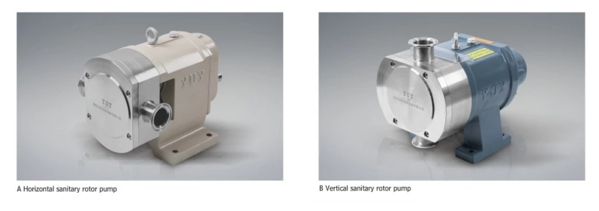
At present,the sanitary rotor pumps can be roughly classified into two types according to the structural form: those with a vertical structure and those with a horizontall structure.As shown in figure A, the inlet and outlet of the pump are parallel to the horizontal direction,and the center line of the two rotors is perpendicular to the horizontal direction.This structure is called a horizontal structure.The vertical structure is opposite to the horizontal structure. The inlet and outlet are perpendicular to the horizontal direction, and the center line of the two rotors are parallel to the horizontal direction, as shown in figure B.
In practical applications,the horizontally-structured sanitary rotor pump is generally used. Since the inlet and outlet are horizontal, it is beneficial for the connection with pipes,and the working efficiency is high. Because the sanitary rotor pump with a verticall structure takes less space, this type of structure will allso be selected in a specific working environment.
Features of sanitary rotor pump:
1. Sanitary and safe
The streamlined structure of the rotor and the pump body cavity are flat and smooth without any dead corner of residues.
There are O-ring seals at both ends of the rotor and shaft to effectively prevent materials from entering the gap between the shaft and shaft hole. The parts contacting the materials are made of stainless steel that meets hygienic standards, and the sealing rubber is non-toxic rubber.
There is a mechanical seal and an oil seal between the pump body and gear box,and the oil stain will not enter or splash into the pump chamber to ensure sanitary and safe transportation of media.
2.Long service life
During the use,there is no hard collision and metal friction between rotors and between the rotor and pump chamber of the rotor pump,so as to improve the service life.
Due to high manufacturing precision, the vibration is small, the operation is stable, and the service life of the seal is increased correspondingly.
Heavy-duty bearings of first-line brands are purchased and helical gears are subject to fine grinding and heat treatment to achieve long life and low noise.
3.Wide application range
The shearing force on the conveyed media is small, and the rotor rotation speed is generally 40-400r/min.The sanitary rotor pump can convey media with a wide range of viscosities as well as fluids with viscosities up to 2 million CP.
Due to the reasonable gap design between the two rotors,the suspension, solid particles and easily crystallized fluids in the conveyed media can be safely transported through the gap.
After equipped with a frequency converter, it can realize control of flow rate and can serve as a common metering pump.
The mobile pump can pump a variety of barreled materials with a suctionvacuum of-0.08MPa.
4.Highly efficient, energy saving and environment-friendly
Practice has proved that the power consumption of the sanitary rotor pump is equivalent to 50%-70% of that of other pumps of its kind,saving social energy.
The gap between rotors and between the rotor and pump chamber of the sanitary rotor pump is small.Even if fluids of low viscosity are conveyed, the return flow generated is small (the return flow is proportional to the gap),which makes the pump flow more stable, the efficiency higher and the suction force better.
Installation requirements
1.The inner diameter of the inlet pipe must be one size larger than the inlet diameter of the rotor pump.The inner diameter of the outlet pipe must be equal to or larger than the inner diameter of the rotor pump outlet.
2.It is strictly forbidden to use a Y type filter or pipeline filter. The effective filtration area of the filter should be more than 2 times larger than the inlet diameter of the pump.
3.The horizontal installation distance of the pump inlet is within 3 meters. It is strictly forbidden to install and use a civil ball valve (its stability is poor and its plug diameter is too small).
Rotor Vane Quantity Selection Reference
| Single impeller | |
| Itis suitable for conveying materials containing large particles. Its unique shape and curve allow it to effectively avoid damage to particles in the material during transportation. The disadvantage is that the outlet flow rate pulsation is high and the pressure is low. | 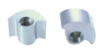 |
| Paddle wheel rotor | |
| It is suitable for conveying large particles.The breaking rate is low,the outlet flow rate pulsation is smaller than that of a single-vane product, and the pressure is lower. | 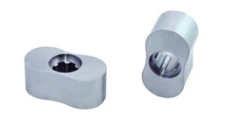 |
| Butterfly rotor | |
| Itis suitable for conveying filling materials containing medium and small particles. The breaking rate is low, the outlet flow pulsation is small, and the pressure is high. | 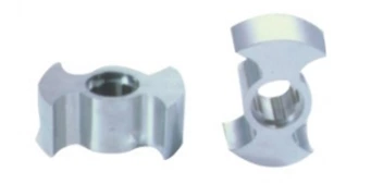 |
| Tri – impeller | |
| As one of the most versatile rotors,its displacement is higher than that of other rotors. There is a certain breakng rate of granular materials. | 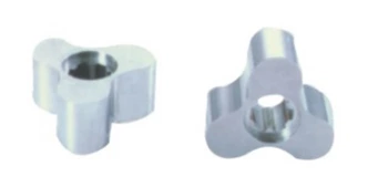 |
| Multi – impeller | |
| With the increase of the blade of the rotor, its displacement will decrease.However,the stability of the conveyed material also blades. There is a high breaking rate of the material particles. | 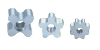 |
Driving configuration
| Equipped with ordinary stepless reducer | |
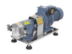 |
Main features: Wide speed control range (the rotation speed can be freely adjusted within 200-1000),continuous operation,stable performance and high flow rate adjustment accuracy.The disadvantage is that the rotation speed needs to be adjusted manually, speed adjustment must be carried out during operation and it is not suitable for use in heavy-load working environments. |
| Equipped with primary stepless reducer | |
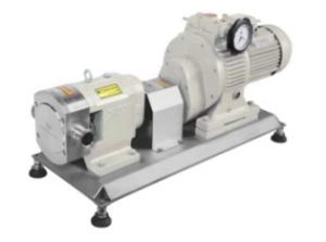 |
Main features: Speed control range 40-500rpm.Compared with the ordinary stepless reducer,its output torque is greater,driving is more steady and performance is more stable under the same power condition.The disadvantage is that the rotation speed needs to be adjusted manually,speed adjustment must be carried out during operation and it is not suitable for use in heavy-load working environments. |
| Eauipped with gear reducer | |
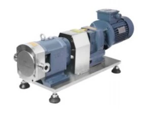 |
Main features: Strong carrying capacity,simple transmission and long service life. In the case of conveying materials of high viscosity,the advantages are obvious.If the variable frequency motor is used with the inverter,the flow can be automatically adjusted. |
| Variable frequency control | |
 |
Main features: Through the frequency converter or digital control,the materials can be conveyed in a quantitative,timed manner at fixed pressure.It can be used as a common metering pump. |
Driving configuration
| Upward incoming and downward outgoing type | |
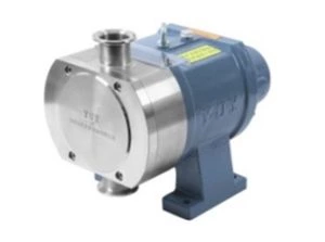 |
Main features: It is used for conveying some materials of low fluidity or used when the space available for use at the site is limited. |
| V port feeding type | |
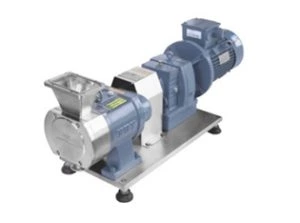 |
Main features: The size of the feeding port is increased to avoid blocking at the inlet.It is suitable for use in service conditions where the materials have very poor luidity and very high viscosity. |
| Installed with safety valve | |
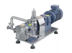 |
Main features: It avoids blocking at the outlet of the pump,which may cause damage to the pump.The safety valve installed can provide protection for the pump and pipe through pressure relief and return flow |
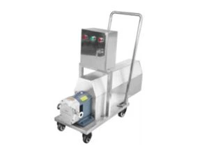
| Installed with trolley and protective cover | |
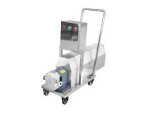 |
Main features: It is applied in applications of non-specified materials.It can be customized according to requirements. |
Sanitary rotor pump head structure and description of parts:
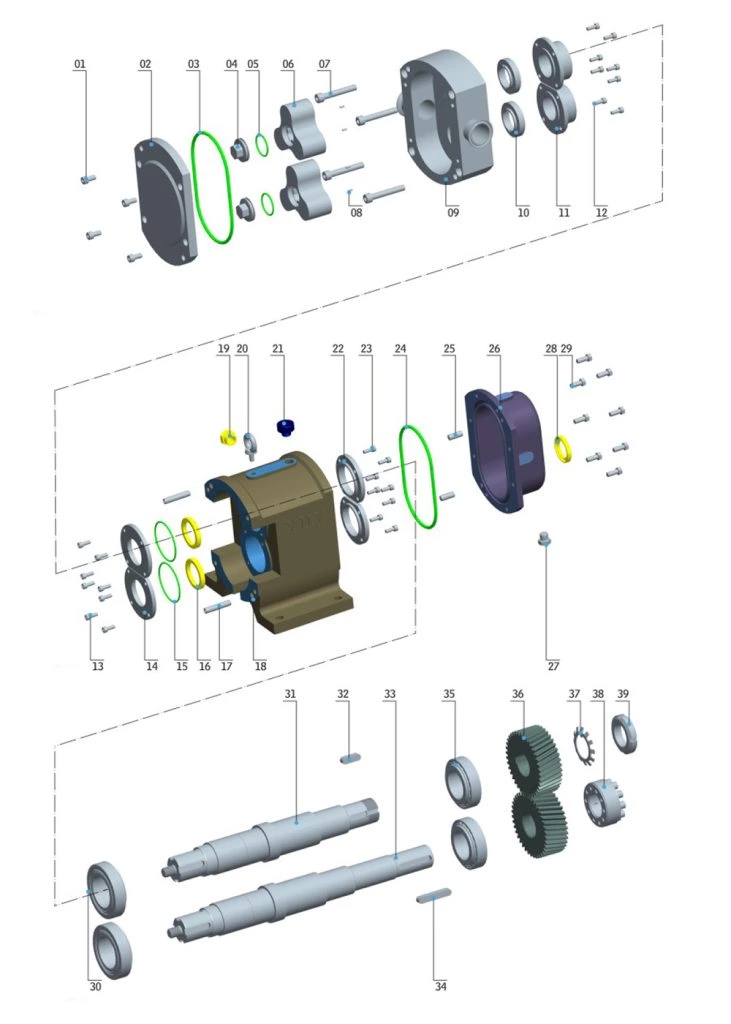
The sanitary rotor pump head is mainly composed of two same rotors,twodriving shafts, pump body, gear box, etc.
Description of parts:
| No. | Name | Material | Quantity | No. | Name | Material | Quantity | |
| 1 | Pump cover lock screw | 304 | 4-8 | 21 | Ventilation cap | 1 | ||
| 2 | Pump cover | 304/316L | 1 | 22 | Rear bearing cover plate | QT250 | 2 | |
| 3 | Pump cover O ring | Fluorine/silica gel/tetrafluonne | 1 | 23 | Rear bearing cover plate lock screw | 304 | 8 | |
| 4 | Rotor locking nut | 304/316L | 2 | 24 | Gear box cover plate O ring | Nitrile | 1 | |
| 5 | Rotor locking nut O ring | Fluorjne/silica gel/tetrafluorine | 2 | 25 | Gear box cover plate locating pin | 431 | 2 | |
| 6 | Rotor | 304/316L | 2 | 26 | Gear box cover plate | QT250 | 1 | |
| 7 | Pump head lock screw | 304 | 4-8 | 27 | Oi plug | 1 | ||
| 8 | Rotor locating pin | 304/316L | 4 | 28 | Framework oil seal | 1 | ||
| 9 | Pump head | 304/316L | 1 | 29 | Gear box cover platesCrew | 304 | 8 | |
| 10 | Mechanical seal dynamicring | 304/316L | 2 | 30 | Front heavy-duty beanng | 2 | ||
| 11 | Mechanical seal staticring | 304/316L | 2 | 31 | Auxiliary shaft | 304/316L/431 | 1 | |
| 12 | Mechanical seal lock screw | 304 | 8 | 32 | Auxiliary shaft flat key | 1 | ||
| 13 | Front bearing cover plate lock screw | 304 | 8 | 33 | Spindle | 304/316L/431 | 1 | |
| 14 | Front bearing cover plate | QT250 | 2 | 34 | Driving flat key | 1 | ||
| 15 | Front bearing cover plate O ring | Nitrile | 2 | 35 | Rear heavy-duty bearing | 2 | ||
| 16 | Frame work oil sea | 2 | 36 | Helical gea | 2 | |||
| 17 | Pump head locating pin | 431 | 2 | 37 | Round nut washer | 1 | ||
| 18 | Gear box | QT250 | 1 | 38 | Expansion sleeve | 1 | ||
| 19 | Oil immersion lens | 1 | 39 | Round nut | 1 | |||
| 20 | Pump head hoisting ring | 1 |
Displacement of sanitary rotor pump
The displacement of the sanitary rotor pump refers to the volume of the media discharged after the two transmission shafts in the pump drive the two rotors to rotate for one cycle,which is usually expressed in such units as ml/r,L/r,etc.The displacement of the sanitary rotor pump depends on the geometric volume of the internal closed cavity.The internal structural sizes of pumps installed with different shapes of rotors are different, so the displacement is also different.
Flow rate of sanitary rotor pump
1.Theoretical flow rate
The theoretical flow rate refers to the volume of the media conveyed in unit time during the working process of the sanitary rotor pump without considering the leakage loss, which is:
Theoretical flow rate = displacement X rotation speed X time
2.Actuall flow rate
The actual flow rate refers to the value calculated after considering the leakage loss during the working process of the sanitary pump.Generally, the volumetric efficiency is between 80% and 90%.
Actual flow rate = theoretical flow rate X volumetric efficiency

Performance selection table:
| Model | Displacement (L/r) |
Rotation speed (r/min) |
Corresponding flow rate (L/H) |
Power (Kw) | Pressure (Mpa) | Maximum viscosity (CP) |
Standard size (mm) |
Connector form |
| YUY-Z-5 | 0.05 | 40-500 | 120-1500 | 0.55-0.75 | 0.1-1.2 | 200 million | φ25 | Olamp Thread Flang |
| YUY-Z10 | 0.1 | 40-500 | 240-3000 | 1.5 | 0.1-1.2 | 200 million | φ32 | |
| YUY-Z15 | 0.15 | 40-500 | 320-4000 | 1.5-2.2 | 0.1-1.2 | 200 million | φ32 | |
| YUY-Z-20 | 0.2 | 40-500 | 480-5400 | 1.5-3 | 0.1-1.2 | 200 million | φ32 | |
| YUY-Z35 | 0.35 | 40-450 | 840-9450 | 2.2-4 | 0.1-1.2 | 200 million | φ51 | |
| YUY-Z-45 | 0.45 | 40-450 | 950-10500 | 4 | 0.1-1.2 | 200 million | φ51 | |
| YUY-Z-65 | 0.65 | 40-400 | 1560-14000 | 5.5-7.5 | 0.1-1.2 | 200 million | φ63 | |
| YUY-Z-80 | 0.8 | 40-400 | 1750-17000 | 5.5-7.5 | 0.1-1.2 | 200 million | φ63 | |
| YUY-Z110 | 1.1 | 40-400 | 2400-23500 | 7.5-11 | 0.1-1.2 | 200 million | φ76 | |
| YUY-Z175 | 1.75 | 40-400 | 3800-37800 | 11-15 | 0.1-1.2 | 200 million | φ76 | |
| YUY-Z-220 | 2.2 | 40-400 | 4750-47500 | 15-18.5 | 0.1-1.2 | 200 million | φ89 | |
| YUY-Z27 | 2.7 | 40-400 | 5800-58000 | 18.5-22 | 0.1-1.2 | 200 million | φ89 | |
| YUY-Z-365 | 3.65 | 40-400 | 7900-78500 | 22-30 | 0.1-1.2 | 200 million | φ102 | |
| YUY-Z-520 | 5.2 | 40-400 | 11300-110000 | 37-55 | 0.1-1.2 | 200 million | φ102 |


