Assembly And Disassembly Methods Of Sanitary Volute Pump
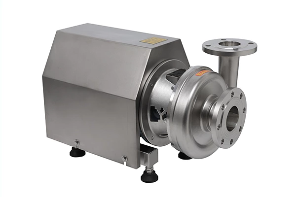
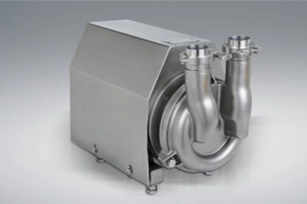
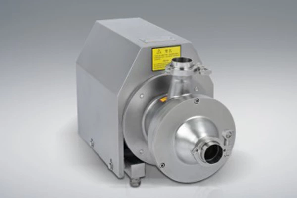
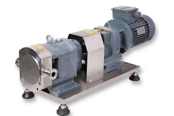
Sanitary Volute Pump is a type of single-suction single-stage or multi-stage centrifugal pump, which is a vertical structure. Because its inlet and outlet are on the same straight line and the inlet and outlet diameters are the same, it resembles a section of pipe and can be installed at any position of the pipe, so it is named a sanitary volute pump. Structural features: It is a single-suction single-stage centrifugal pump, with the same inlet and outlet and on the same straight line, perpendicular to the center line of the shaft, and a vertical pump.
Key points for use
1. Test run: Check whether the connector is loose; turn the coupling by hand to make the rotor rotate several times to see whether the unit rotates flexibly, whether there is a sound and uneven feeling, to judge whether there is foreign matter in the pump or whether the shaft is bent, whether the seal is installed correctly, etc.; check whether the clean No. 20 lubricating oil in the sealing chamber is filled with 1/2 of the cavity space; whether the surface of the pump unit is clean; the unit is turned to no-load test.
2. Manual start: Fill the pump (first time), open the outlet valve slightly, start the motor, and gradually open the outlet valve to the working condition requirements when the pressure rises and confirms that the pump unit is running smoothly.
3. Operation inspection: When the sanitary volute pump is operating normally at the power frequency, the readings of the pump group's ammeter, voltmeter, inlet and outlet vacuum gauges, pressure gauge and flowmeter should be checked and recorded regularly to see whether the vibration, noise, temperature rise, etc. of the unit are normal. There should be no obvious aviation oil leakage at the shaft seal.
4. Normal parking: Close the discharge valve, make the pump lightly loaded, and stop the motor.
Emergency parking conditions:
⑴ The pump motor working ammeter indicates abnormality (excessively large or becomes very small); the pump system makes abnormal noises.
⑵ The pump inlet vacuum pressure gauge and outlet pressure gauge indicate abnormalities, the pump body vibrates greatly and makes abnormal noises, and the performance is seriously reduced.
⑶ The pump motor produces odor, aviation oil leaks from the shaft seal, and the bearing temperature exceeds 75 degrees.
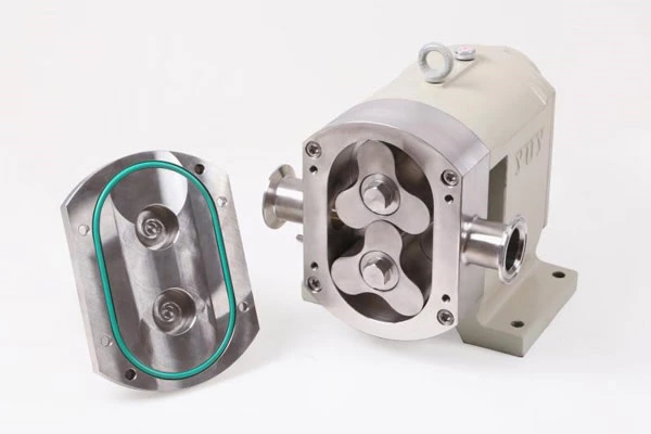
Assembly and disassembly of the pump
Before assembling the pump, all parts should be checked. The mating surfaces of the parts, especially the friction surfaces of the mechanical seals, should be cleaned. The sealing surface should not have obvious scratches, cracks, bumps and other defects. If there are the above defects, it should be replaced.
Assembly:
Press the water retaining ring onto the motor shaft and fasten the middle seat to the motor with bolts.
After applying lubricants such as vaseline on the rubber ring of the mechanical seal static ring, press the static ring assembly into the middle seat along the shaft, apply clean grease on the sealing surface, install other sealing components, install the flat key, impeller and retaining washer, and tighten with bolts.
Note: The sealing rubber ring of the mechanical seal static ring is easy to deviate during installation, which will cause the mechanical seal to leak. Careful inspection should be made during installation.
Apply a proper amount of grease on the sealing end surface of the middle seat and install the O-ring. When installing the O-ring, the sealing ring is easy to fall off and fold. Please be careful to avoid water leakage.
Lift the motor assembly, with the impeller facing down, slowly insert it into the pump body, then tighten it with bolts, and install each pipe plug and bleed plug.
Turn the rotor by hand to check if there is any jamming.
Disassembly:
Perform the installation in the opposite steps.
Note: When disassembling the mechanical seal, do not use a hand hammer or a hammer to directly hit the static ring. Use wood to gently knock and slowly remove the static ring. If there is dirt accumulation that makes disassembly difficult, it should be cleaned before disassembly.
Installation, operation and maintenance of the unit:
Installation:
When installing, the place closest to the conveying liquid should be selected so that the pump is installed at the place with the minimum suction height and the shortest suction pipeline
Note: The distance between the unit and the surrounding obstacles should be greater than 150㎜ so that the motor fan has sufficient air source.
When the pump is used in places with strict vibration requirements, a shock absorber (pad) can be used and must be installed according to the manufacturer's instructions.
The installation of the pipeline should be reliably fixed, and the pipeline support close to the pump flange should be sufficiently rigid, and the pump should not be allowed to bear the weight pressure of the pipeline.
The installation of the pump unit should avoid direct sunlight and rain.
A vacuum pressure gauge should be installed at the inlet of the pump, and a pressure gauge should be installed at the outlet flange to observe and control the operation of the pump. The range of the pressure gauge should be 2~3 times the actual pressure.
The pump inlet and outlet pipes should be equipped with gate valves to facilitate maintenance and operation adjustment.
Wiring: The wiring must be done correctly according to the nameplate requirements. When wiring, the terminal must be firm and no looseness is allowed, otherwise, it will cause poor contact and cause the motor to burn out due to lack of phase. To ensure the reliable operation of the motor, an overload protection device should be installed at the electrical switch, and the setting value of the protection device should be adjusted according to the current requirements on the motor nameplate.
Warning: If the overload protection device is not installed, the motor will burn out due to overload when the outlet valve is fully opened, when the flow rate is too large, or when the current suddenly increases under certain circumstances.
In the suction state (the water level is lower than the impeller axis or the water level is lower than the pump suction port axis), at standard atmospheric pressure, the installation height of the pump
H安=10-(NPSH)r-0.5-hw, hw is the resistance loss of the suction pipeline (the calculation unit in the formula: m). When pumping water from a pool, the length of the straight pipe section before the pump suction port should not be less than 3 times the inlet diameter, and the depth of the suction pipe port immersed in the water surface should be greater than 1.5 times the inlet diameter and not less than 500㎜. The distance between the suction pipe port and the pool wall should be greater than 1.5 times the diameter, and the distance from the pool bottom should be greater than 1.5 times the diameter and not less than 500㎜, and a filter should be added, and the total area of the filter should not be less than 2~3 times the area of the suction pipe port.
Note: The installation of the horizontal section of the suction pipe should be slightly tilted downward against the direction of the water flow to prevent air traps.
In order to facilitate the filling of water into the pump before starting, a bypass valve can be added at both ends of the check valve. Before the pump is started, open the bypass valve to fill the pump with water, and close it after filling, which is convenient for use. For pumps used for water supply to high-rise buildings or with an outlet pressure greater than 0.2MPa, in addition to the gate valve installed at the discharge port, a check valve should also be installed between the pump outlet and the gate valve to prevent sudden power outages and high-pressure water backflows that may damage the impeller.
Operation:
Open the inlet valve and bleed plug, close the outlet gate valve, fill the pump with water and close the bleed plug.
Before starting, use a screwdriver to move the fan blades of the water pump motor to check whether the motor runs smoothly.
Momentarily start the motor to determine whether the rotation direction of the pump shaft is consistent with the rotation direction marked on the pump (clockwise rotation from the motor end).
Warning: It is strictly forbidden to test run the pump when there is no water in it to avoid damage to the mechanical seal.
When the inlet gate valve is fully open and the outlet gate valve is closed, start the water pump, turn on the pressure gauge, and gradually open the outlet gate valve until the required operating condition (when the outlet gate valve is closed, the operating time should not exceed 3 minutes). Note that the current of the motor during operation does not exceed the rated current.
Note: The flow rate at the operating condition point should not be greater than the maximum flow rate given in the performance table. During operation, the actual head H=(Pout-Pin)/0.0098 should not be less than the head corresponding to the maximum flow point given in the performance table (in the formula, Pout is the value of the pressure gauge at the outlet, Pin is the value of the vacuum pressure gauge at the pump inlet flange, pressure unit: MPa, head unit: m). The ideal and efficient operating condition is the middle point given in the performance table. The outlet gate valve control can be adjusted by observing the inlet and outlet (vacuum) pressure gauges.
If the device (pipeline) characteristic curve is determined, if the operating condition of the pump is to be adjusted, the best method is to change the speed or adjust the impeller diameter. Please consult the manufacturer for the implementation plan.
Shutdown sequence: Close the gate valve on the discharge pipeline----motor---pressure gauge.
Maintenance:
Check whether the operation is stable, the wear and leakage of the mechanical seal, and replace the seal in time to prevent pressurized water from entering the motor.
Check the temperature change of the motor housing frequently. The pump operates normally and the motor temperature rise is allowed to reach 80℃. If necessary, further check whether the motor current is overloaded and the three-phase current is unbalanced.
Check the water inlet pool frequently for floating objects and water level changes. If the water inlet pool drops below the minimum water level, the pump should stop running to avoid cavitation and damage to the impeller. If necessary, adjust the gate valve to appropriately reduce the water output of the pump to promote the water level of the pool to rise.
Pay attention to the changes in the pressure gauge and ammeter, and take corresponding measures in time if any abnormality is found.
When the pump is out of use for a long time, drain the accumulated water, remove rust, and apply anti-rust grease.